Extrusion die bearing design controls how aluminium flows through the final shaping surfaces of a die. For UAE extruders, the aim is a profile that exits evenly and meets its drawing requirements under the intended production conditions. A bearing should therefore be designed together with the profile geometry, alloy, die support and press process.
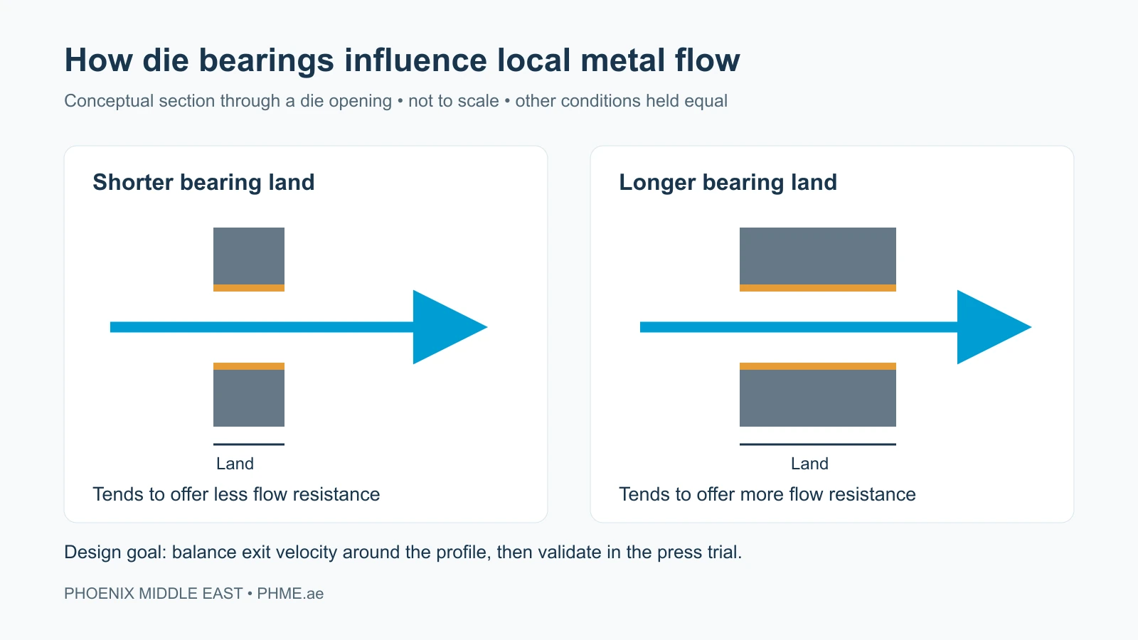
A longer bearing land generally adds local flow resistance, while a shorter land generally reduces it. That principle is useful, but it is not a universal correction rule. Changing a bearing without identifying why one part of the section is moving differently can create a new problem elsewhere.
What is the bearing in an aluminium extrusion die?
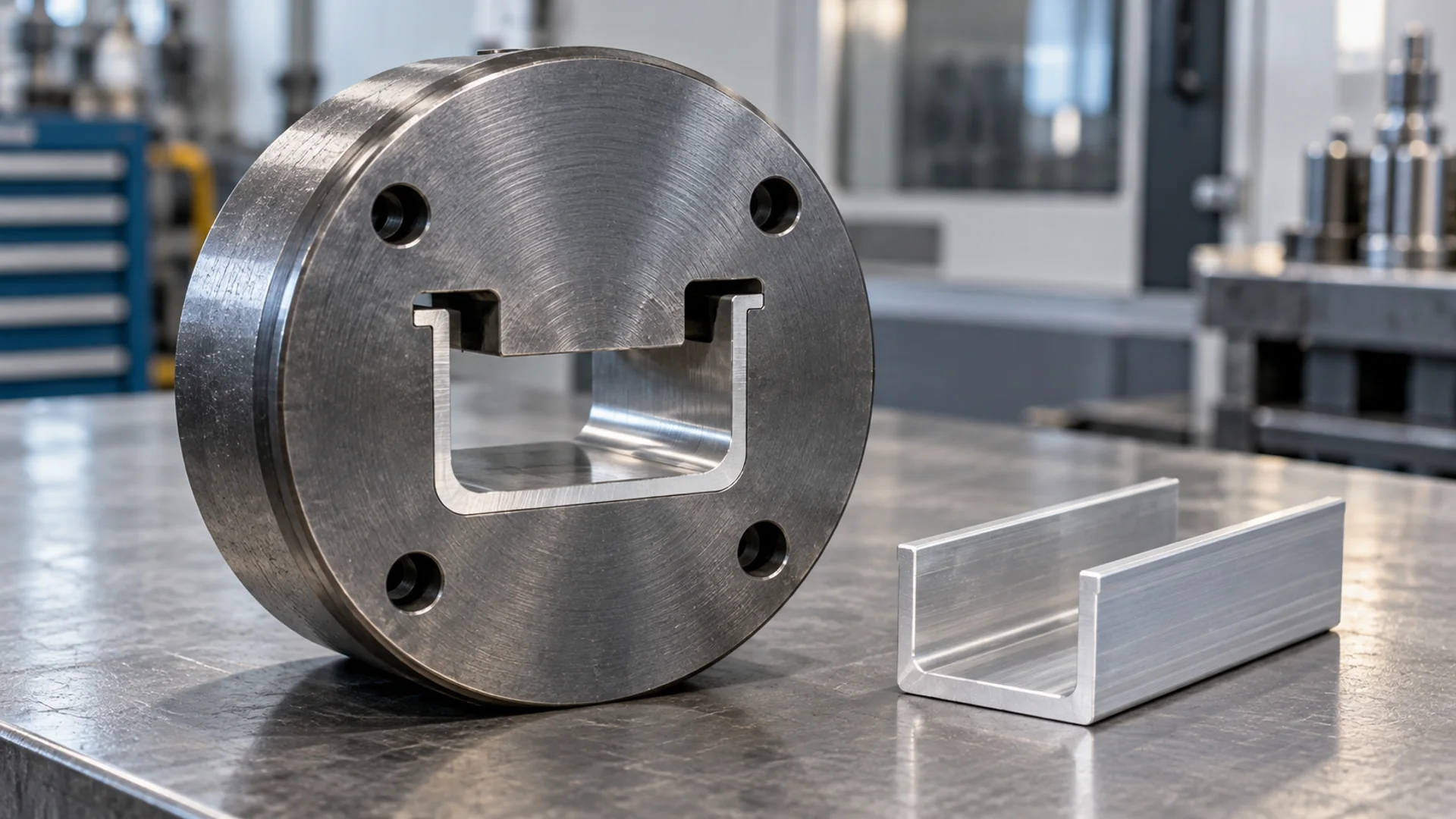
The bearing, also called the land, is the working surface along the die opening that contacts the aluminium as it takes its final cross-sectional shape. Its effective length, condition and geometry influence local resistance to flow. The Aluminum Extruders Council explains the relationship between bearing length and flow control, including the need to balance metal movement across a section.
A profile with a thick base, thin legs and an offset feature does not present the same flow conditions everywhere. Specifying one bearing length around the whole opening may be inappropriate. Designers consider the complete section and the supply of metal to each region, not just the final outline.
Why balanced flow matters to the finished profile
If neighbouring regions leave the die at different speeds, the emerging section can distort. In production, an investigation may start with bow, twist, dimensional variation or a feature that repeatedly needs correction. These observations help define the problem; none proves that bearing length alone is responsible.
For example, a channel with one thin leg and a heavier opposite wall requires a review of both flow distribution and structural support. The useful question is not simply whether to shorten a land. It is whether the die design and operating conditions allow the whole section to emerge in a controlled way.
What affects extrusion die bearing design in UAE production?
Profile geometry and die type
Wall thickness changes, narrow tongues, unsupported features and the location of each opening all belong in the design review. Solid and hollow tooling also distribute metal differently. Start by selecting the appropriate extrusion die type, then develop its flow-control details.
Alloy and the intended operating window
State the alloy, billet and die temperature ranges, press information and intended production conditions in the enquiry. A design approved for one operating window should not automatically be treated as validated for another. Record the conditions during trials so that later comparisons are meaningful.
Tool support and surface condition
The die assembly must support the working geometry under load. Wear, damage or deposits at the working surfaces can also change how a previously successful die behaves. A bearing review should include inspection of the tool and its support, rather than assuming every change in the extrusion comes from the original design.
A practical workflow from drawing to press trial
- Define the acceptance criteria. Mark critical dimensions, mating surfaces, visible surfaces and any straightness or twist limits. Explain how the part will be assembled and finished.
- Review the complete flow path. Consider the profile, metal feed, bearing arrangement and die support as a connected design. For complex sections, assess whether simulation would help evaluate alternative arrangements.
- Document the initial design. Retain drawing revisions and the intended process conditions. A controlled baseline makes trial feedback useful.
- Measure the trial profile. Record the location and direction of deviations, together with operating conditions and the measurement stage. Label samples so the results can be traced to the correct run.
- Make and verify a targeted correction. Agree a specific tooling or process change, then compare the next trial against the same acceptance criteria.
Research on optimising bearing lengths in aluminium extrusion dies treats flow balancing as an iterative design problem. Simulation can help assess a proposed arrangement, but the production trial and dimensional inspection remain essential. PHME’s guide to extrusion flow simulation explains where this fits in the broader development process.
When should a bearing be corrected or maintained?
Distinguish a new die that has not yet met its target from a proven die whose results have changed over time. The first situation may require design correction. The second calls for a review of wear, surface condition, handling and changes in the production process before deciding what to alter.
Send the die history, marked samples and trial records with a request for die correction and optimisation. For a tool with surface deterioration, discuss die re-polishing and maintenance. Removing material is not reversible through a process adjustment, so a correction should follow a documented diagnosis.
Common questions about die bearing design
Is a shorter bearing always better for extrusion speed?
No. Lower local resistance is only one consideration. The profile still needs balanced flow, appropriate surface quality and dimensional control. Choose a validated design and operating window rather than a minimum land length in isolation.
Can one bearing length be specified for every profile?
No. Geometry, alloy, metal feed and tooling arrangement differ between profiles. A dimension that works on one die is not automatically suitable for another.
What should a UAE extruder send for a bearing-design review?
Provide the profile drawing or CAD file, alloy and temper, press details, critical tolerances, surface requirements and intended volume. For an existing die, add its revision history, photographs of the working surfaces and labelled trial measurements.
Plan the bearing with the whole die design
Effective extrusion die bearing design in the UAE starts with the actual production requirement. PHME’s design, engineering and prototyping service brings drawing review, flow considerations and trial feedback into that discussion. Share the complete application so that the bearing arrangement can be developed and checked as part of a workable tooling solution.